

An Avionics System of EPIC Proportions - Part one of two
In the world of avionics systems, it seems that about every 18 months or so manufacturers come up with what they consider to be the latest and greatest system to have in our aircraft. Their marketing departments have to come up with something snazzy to catch our attention. After all, they can’t sell us something we need if we don’t know we need it! Once the system is on our aircraft, what do we really know about it from a maintenance perspective? Is it one system or several subsystems tied together in some way to offer the operator a “complete avionics suite?”
In the December 2010 issue of then Helicopter Maintenance(then called HeliMxmagazine), I wrote an article on federated, integrated and distributive architecture avionics systems. In this two-part article, I am going to revisit the distributive system, specifically the one installed on the AgustaWestland AW-139 helicopter. This system is called Primus EPIC and it is manufactured by Honeywell International Inc. Part one in this issue will be an introduction to the system’s architecture and major LRUs. Part two will run in our April/May issue and will discuss the major subsystems of the Primus EPIC system in the AW-139 helicopter. All photos and diagrams shown here are courtesy of AgustaWestland.
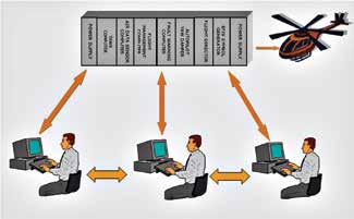
Distributive architecture is very much like a personal computer (PC). The hardware is generic and designed to run many different software programs. The only catch is that the software must be able to run on the operating system. My PC runs many programs and uses Windows as its operating system. Likewise, the operating system for the Primus EPIC system on the AW-139 is called the Digital Engine Operating System (DEOS) and it runs all the EPIC software.
Distributive System Essentials
The distributive system reduces LRU weight, space, power consumption and wiring in the aircraft. LRUs have become modules that fit into a cabinet or rack. An aircraft can have multiple racks and the racks may hold a different number of modules. The modules are mostly the same from a hardware perspective, but run functionally-specific software. This scalability gives a distributive system the ability in a cost-effective manner to fit a multitude of aircraft with different avionics requirements. A good analogy would be similar to several desktop computers connected together and sharing processors and memory and the ability to run several software programs at the same time.
The modules in the distributive system use microprocessors similar to those found in PCs. The use of commercial off-the-shelf (COTS) hardware helps reduce the cost of engineering specific hardware for each function required. Since the system is now software based, it is also easier for the end user to upgrade changes and improvements to the system. Instead of having to send an LRU back to the manufacturer for an update, it is possible in many instances to have the software loadable in the field. The information is displayed on the electronic display system (EDS) flat panel displays on the flight deck. These include primary flight displays (PFDs), multifunction displays (MFDs) and engine instrument and crew alerting system (EICAS) displays. The EICAS display is one of many displays presented on the MFD.
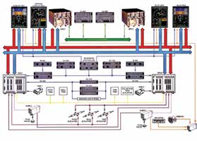
An essential function of a distributive system is information exchange in and between subsystems. Most of the information transfer is accomplished through the use of digital data buses. Some of the data transfer is accomplished in the form of discrete data. Again, this is a tremendous savings on weight and wiring requirements. The EPIC system also uses a local area network (LAN) in the aircraft for specific use.
The distributive system also has its own unique requirements when it comes to maintainability. Built-in-test (BIT) is essential. Test equipment required may include bus readers, dual trace oscilloscopes and signal generators (to check out bus wiring). In removing and replacing modules, it becomes imperative to adhere strictly to the procedures called out by the avionics manufacturer and those listed in the instructions for continued airworthiness (ICA). Static electricity, proper grounding techniques and handling and shipping can all cause problems and should not be taken lightly.
Maintenance Features
There are several maintenance approaches to distributive systems that are currently in play. Some key maintenance features are:
• A single-point access to all subsystems.
• The BIT is simple to operate.
• The BIT can be run from both inside the aircraft and from an external access point.
• The BIT is able to determine the root cause of a failure and eliminate cascading faults.
• Maintenance messages are cross referenced to failures and EICAS messages.
Lastly, with an eye towards returning the system and aircraft to a no fault state, the central maintenance computer (CMC) provides an EICAS message to maintenance message correlation. This allows the maintenance professional to determine the source of the problem and the necessary corrective action to be taken.
The CMC is not intended as the “final judge” of system health for the purposes of airworthiness, dispatch determination and safety. That role is fulfilled by the CAS portion of the EICAS display. The indication that a return to service procedure has been completed successfully is the clearing of all associated CAS messages.
EPIC Architecture
A key driver of the EPIC design was the creation of a single architecture that could cost effectively span a wide range of both fixed-wing and rotary-wing aircraft. With generic hardware and aircraft specific software, this is easy to accomplish from an engineering standpoint.
An easy way to view the overall system is the same way one would go about eating an elephant … one bite at a time. Keep in mind that the functions of the EPIC system remain the same as in federated and integrated systems, but the packaging (architecture) has changed.
The system’s major LRUs are the:
• Modular avionics unit (MAU)
• Modular radio cabinet (MRC)
• Displays (PFD and MFD)
• Air data module (ADM)
• Controllers
• Multifunction control display unit (MCDU)
The key subsystems are:
• Automatic flight control system (AFCS)
• Communications
• Indicating and recording
• Navigation
• Flight management system (FMS)
• Attitude heading reference system (AHRS)
• Weather radar
• Radio altimeter
• Central maintenance system
Due to the deliberate open architecture of the EPIC system, third-party manufacturers can interface with the system in one of four different ways:
• Third-party module in the MAU
• Third-party software in a processor module
• Stand-alone LRU that uses ARINC 429 as a digital interface
• Stand-alone LRU that uses avionics standard communications bus (ASCB) as a digital interface.
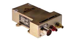
Primus EPIC Major LRUs Modular Avionics Unit (MAU)
The MAUs are the heart of the Primus EPIC system. They each have nine slots on the AW-139. This LRU houses most of the systems processors, software programs, memory and network interface controllers that allow the EPIC system to function.
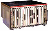
Each MAU has a number of user slots. The slots by design can hold single and dual slot field removable modules. The term “user slot” indicates that it is available for a user (subsystem) or aircraft manufacturer to use for specific aircraft requirements. The MAU also houses power supply modules and network interface controller (NIC) modules which are not counted as user slots, but in addition to them.
Configuration Module
The EPIC systems on the AW-139 utilize system configuration modules, sometimes referred to as aircraft personality modules. These are located in what is called the backshells of the MAU’s timing network interface controller (TNIC). The configuration modules remain with the aircraft in the event of a TNIC module or MAU cabinet change.
MAU Basic Modules
The MAU modules in the AW-139 are as follows:
• Processing module (PROC)– This is a general purpose computing module similar to those found in PCs. It runs on the DEOS and can host multiple functions with different software.
• Network interface controller/processor(NIC/PROC) – This module is a combination of a NIC and processor in one module. The NIC provides the interface for the MAU to various digital buses.
• Input/output (I/O) modules– These modules control the flow of data both to and from the MAU. This includes generic and custom I/O functions, display control I/O and AFCS actuator I/O.
• Database module (DBM)– The DBM is a general purpose file server module that contains database and back-up program file information.
• Power supply module (PSM)– This module provides power for all the modules in an MAU channel. The module can provide up to 290 watts of power and supply a variety of DC voltages.
Air Data System (ADS)
As with most traditional air data systems, this one provides and displays airspeed, barometric altitude, vertical speed and temperature on the EDS. Although you might not think of an air data system as a navigation tool, in the Primus EPIC system on the AW-139, air data parameters are also sent to a host of other systems. These include the automatic flight control system (AFCS) and the flight management system (FMS), to name a few.
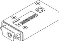
In the EPIC system on the AW-139, the pressure-sensing elements of a traditional air data system are remotely mounted and self-contained in the AZ-200 air data modules (ADMs). Standard pitot-static lines are plumbed to the ADM, and the ADM transmits this data to the air data application (ADA) hosted on a processor module in the MAU. Pitot-static, TAT, baro settings and the ADA comprise the ADS in the AW-139.
Modular Radio Cabinet (MRC)
At the center of the Primus EPIC radio system are the two modular radio cabinets (MRCs). Each cabinet hosts a VHF communication radio, VHF navigation and DME radios, an ADF function, a selective calling (SELCAL) feature, a digital audio system, and links to the cockpit voice recorder (CVR) and the cabin public address system. The MRC also provides a communications link from the cockpit audio system to the high-frequency (HF) radio if one is installed as an available option.
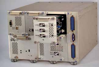
The following line replaceable modules (LRMs) are located in the MRC:
• An ADF module
• A DME module
• A VHF NAV module
• A VHF COM module
• A mode S transponder
• A network interface module (NIM)
• An aircraft personality module (APM)
The NI-900 NIM is an LRM located on the far right side of the MRC with a handle between two receptacles. It provides the electrical interface between other aircraft systems and the MRC modules.
Frequency selection, channel and mode control is provided by the multifunction control display unit (MCDU) and cursor control device (CCD) working together with the EDS and FMS functions that are housed in the MAU. The NIM helps transfer all the radio data to the appropriate digital buses.
When it comes to the APM, one of four is located in the backplane of each MRC. The MRC configuration and some audio levels are stored in this module. This module is not field replaceable.
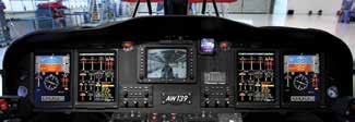
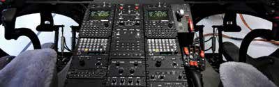
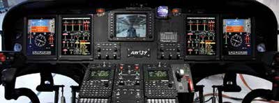
Electronic Display System (EDS)
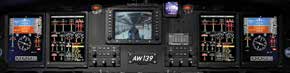
The EDS on the AW-139 is quite an eyeful to see. There are two to four liquid crystal displays (LCDs), depending on the aircraft configuration. They provide the flightcrew with most of the visual data needed to fly the helicopter. The LCDs are identical and interchangeable, with their mounting position in the instrument panel deciding what they will display (PFD or MFD).
Each LCD is divided into sections for the display of different flight, navigation and communications information.
Primary Flight Displays (PFDs)
The PFD displays attitude, heading, airspeed, barometric altitude, vertical speed and radio altitude readouts. The PFD also displays autopilot status and flight director command bars and mode annunciations. Other displayed information includes navigation data, radio tuning data and critical rotor data including power index, engine speeds and rotor speed. The PFD can also have weather radar or terrain information displayed on the horizontal situation indicator (HSI) portion of its display.
Display Controller
The PFDs are controlled by the display controller (DC). This controller allows the flightcrew to change settings and select navigation data and weather radar or terrain data to be displayed.
Multifunction Displays (MFDs)
The MFD is typically used to present primary engine instruments and crew alerting messages (EICAS). It also displays expanded navigation data as a function of navigation systems in the EPIC installation. The MFD, like the PFD, is divided into fixed sections for data display. There are many different displays available, all selectable by the flightcrew. However, we won’t go into great detail here, as this is an overview of the EPIC system. The MFD upper window is accessible to the flightcrew through the use of the virtual buttons and a set of drop-down menus.
The upper window can display power plant data as well as system pages like electrical, hydraulic, AFCS and maintenance pages, to name a few. The upper window can also display two selectable navigation formats, MAP mode and PLAN mode. The MAP mode resembles a standard HSI-type presentation, while the PLAN mode offers a true north presentation.
The lower window displays secondary engine and system data, as well as messages from the crew alerting system (CAS). The MFD is controlled by virtual buttons along the top of the display and by a cursor control device (CCD).
Cursor Control Device (CCD)
The CCDs, one each for the pilot and co-pilot, provide the following capabilities for the FMS function:
• Map geographical flight planning
• Radio tuning
• Range control
• Menu selection
Multifunction Control Display Unit (MCDU)
For Primus EPIC, Honeywell has replaced the traditional FMS control display units (CDU) and radio management units (RMUs) with MCDUs. In addition to control of the FMS, the MCDU controls radio tuning.
If you were not familiar with the Primus EPIC system, you have now had a brief overlook at its architecture and major LRUs. Join us again with our next issue of HMMfor part two, in which we will discuss the major subsystems of the Primus EPIC system in the AW-139 helicopter.