

Demystifying COMPOSITE REPAIR IN MODERN ROTORCRAFT
Unless you’ve been living under a rock for the past 20 years, the proliferation of advanced composite materials in the rotorcraft industry cannot have escaped your attention. Throughout the 1990s and even into the new millennium, it seemed that with every new model helicopter introduced, yet another portion of the structure that we were accustomed to being made from aluminum was suddenly made from an advanced composite material, like carbon fiber, fiberglass or Kevlar. Perhaps it’s just my perception as an old sheet metal guy, but that trend seems to have increased dramatically in the last six to eight years.
The trend towards advanced composite materials is not a conspiracy to make our sheet metal skills obsolete, but rather a natural evolution in the never-ending battle against the helicopter’s oldest enemy: weight. As such, we must embrace its coming and endeavor to expand our skill set to include an understanding of how composites work and how to repair them properly.
Composite Basics
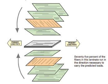
When we talk about advanced composite materials in aerospace, we’re referring to long-fiber reinforcements such as glass, carbon or Kevlar (aramid) embedded in a matrix material, usually an epoxy resin. For the most part, the loads within a structure are borne by the fiber reinforcement. This being the case, multiple plies of the reinforcement are typically laid up and oriented specifically to handle the loads imposed on the part (Figure 1). While short, chopped fiber and polyester resin construction like you might find in a hot tub or shower stall are also composites, we generally don’t refer to them as “advanced composites,” because they simply aren’t able to achieve the same strength-to-weight ratios as their aerospace counterparts.
Strength to Weight Ratios
Advanced composites are all about strength-to-weight ratios, or how strong a part is relative to its total weight. When the newest model of an old, familiar airframe makes its debut sporting an all-composite tail boom, one of the first things you may hear is that the new structure is stronger than the metal version. This is a common misconception. Assuming the loads on that tail boom haven’t changed, the new composite tail boom won’t be any stronger than the old one, but it will be lighter, and sometimes dramatically so.
 A significant decrease in weight does a couple of things for us. First, it shifts the c.g. forward. This is a huge advantage on any aircraft with aft c.g. problems. If you’re like me, you can probably think of several aircraft right off the bat that could benefit from such a modification. Second, it decreases the overall weight and results in an increased useful load, range and a general (but sometimes subtle) increase in overall performance.
One of the major reasons for this substantial decrease in weight stems from the fact that metals are isotropic materials, meaning that their strength is essentially the same in every direction. On the other hand, advanced composites only exhibit strength in the directions in which fibers are running. This means that by orienting the fibers in specific directions, we can engineer the part to be strong along all the axes in which we need strength. Conversely, we reduce or eliminate fibers in directions in which strength is not necessary. The end result is a part that only has strength in the directions it requires to perform its function, thereby saving weight.
Repair of Advanced Composite Structures
As the manufacturing paradigm shifts from aluminum to composite structures, so must our understanding of how these materials are repaired … lest we find ourselves unemployed. From our first class in repair of metal structures, it’s obvious that what we’re trying to do is restore the load path to the damaged area. The same is true for composite structures of course, but in order to make sense out of the repair procedures we have to take into account the fundamental differences between metals and composites.
Let’s use a simple punctured skin in a semi-monocoque structure as an example. With metals (isotropic materials), we simply follow some old, familiar and long-established “rules” to:
1. Clean up the damaged area.
2. Select a patch material – same alloy and thickness (or one thickness greater).
3. Select the appropriate number, alloy, diameter and length of rivets.
4. Lay out the rivet pattern observing rules concerning pitch, transverse pitch and edge distance.
5. Install the patch.
I left out some detail, but you get the point. Most of the standard practices for sheet metal repairs date back almost 90 years. A good structures mechanic can recite the formulas standing on his or her head. Advanced composite materials have “rules” too. It’s just that most of us aren’t as well-versed in these rules as we are in those pertaining to sheet metal. Once we begin to understand these new rules, we begin to understand what we’re being asked to do in a composite repair procedure, and how it differs from what we’re accustomed to.
In a similar repair to a composite skin, we would also start by removing the damaged material. Not too surprisingly, the end result would look essentially the same as with a metal structure – with gently radiused corners, or preferably an oval or circular shape in order to avoid any stress-risers that might cause cracking later on. The major difference here is that the cutting/machining tools used for composite materials are often quite different than those used on sheet metal. While in both cases we might use a 90-degree die grinder, the “bit” or cutting tool itself would need to be a diamond abrasive router bit (for glass and carbon), or a router bit specifically designed for cutting aramid laminates.
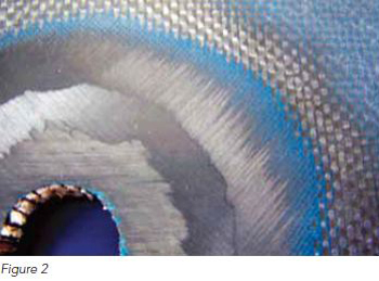 Now, since we know that a composite laminate transfers loads based on the orientation of the plies within it, it’s obvious that any patch used to repair that laminate must have at least the same number of plies at the same orientations as the original laminate. This being the case, you may be asked to taper, sand or step the edge of the repair to expose underlying plies. Exposing these plies allows us to apply a patch in which each ply of the patch is bonded to its counterpart within the laminate being repaired (Figure 2).
In many cases, however, the repair manual will not call for a scarf or a step and simply require a scab patch. Even with scab patches, you will find that the number of plies and their orientations specified by the repair procedure closely mimic those found in the original laminate. It is also common with both methods to see one or more additional repair plies called out in the procedures. This is due to the fact that the processing methods available to us for field repairs are usually less sophisticated than those used to manufacture the part originally. This results in a repair that may have less strength than the surrounding laminate. By adding extra plies to many repairs, engineers ensure a positive margin of safety.
Mixing and Applying Resins
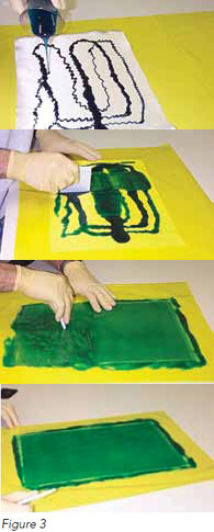
The vast majority of field-level repairs for helicopters are wet lay-up repairs. This means we start with dry fabric (glass, carbon, or aramid) and we impregnate it using the correct amount of properly mixed epoxy resin (Figure 3). There are two key elements here: what constitutes “properly mixed” and what is the “correct amount.”
Remember all that basic math you didn’t think you’d need after high school? Well, it’s about to come back to haunt you, just as it did me. Epoxy resins are furnished as two-part systems, Part A (the base resin) and Part B (the hardener). Known as the mix ratio, the amount of Part B added to Part A is critical. If the instructions for mixing and curing are not followed carefully, the cured resin in the repair may not have sufficient properties to be airworthy and catastrophic failure may result. A corollary to sheet metal repairs would be to use untempered aluminum (O-material) in a patch. We simply wouldn’t do that because we know it would fail. Similar consideration should be given to the epoxies we use in composite repair.
 Understanding the mix ratio as it’s presented on the container or instructions is key to mixing your resins and adhesives properly. Let’s consider a mix ratio of 100:42. When posed as a mathematical word problem, a mix ratio of 100:42 would read something like this: “To 100 parts-by-weight of Part A, add 42 parts-by-weight of Part B.” A simple, easy-to-remember method for converting a ratio to a percentage is found below:
Ratio as seen in instructions 100 : 42
Change the colon to a “plus” sign100 + 42
Add 100 + 42 = 142
Divide the addends by the sum = 0.7, or 70% = 0.3,or 30%
From here we can properly mix any amount of resin because we know that 70 percent of the total weight is Part A and 30 percent is Part B.
Fiber/Resin Ratios
For optimal performance, composite laminates should contain a specific percentage of resin by weight. We call this the fiber/resin ratio. For example, a very common aerospace fiberglass fabric (style 7781) performs best if approximately 60% percent of the weight of the laminate is fiberglass and the remaining 40 percent is the epoxy resin matrix. This fiber/resin ratio would be expressed as 60:40. Having significantly more resin than this does not make the laminate stronger; it only makes it heavier and stiffer. Having significantly less resin than desired causes some of the laminate’s physical properties to fall off rather quickly, most notably its compressive strength. Because carbon fiber weighs less than glass, desirable fiber/resin ratios tend to be closer to 45:55. For aramid fabrics, which are lighter still, you’re looking for about 40:60.
Simple enough, right? Here’s the problem – if you mix up a batch of resin equaling 40 percent of the finished laminate, you’ll quickly find out that it just isn’t enough to wet-out the repair material sufficiently. Generally speaking, you’ll find that the amount of resin you need is at least half again the weight of the fabric. Expressed as a fiber/resin ratio, that’s 40:60. So, using fiberglass as an example again, how do we get from 40:60 to the desired 60:40 as the resin cures? The answer is as much art as it is science.
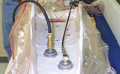
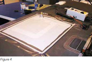 Vacuum bagging has been used to apply pressure to repairs of all sorts for decades. A simple vacuum bag like the one seen in Figure 4 actually performs two tasks for us in a repair. First, the use of a vacuum bag allows for the extraction of air and volatiles from the resin. Second, it provides uniform pressure to the patch as it cures. The physics involved are fairly simple. By drawing the air out from inside the bag, atmospheric pressure pushes down on the outside of the bag. Atmospheric pressure is about 14.7 psi (22 in/hg) at sea level, so you can see how we can develop substantial, uniform pressure on our repair area using very lightweight materials.
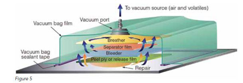
Between the vacuum bag and your patch, there will be a bleeder schedule and a breather. The bleeder schedule is a series of materials applied to the patch in such a way that they serve as a conduit allowing gasses to escape, while also wicking away the resin in excess of our desired 40 percent (Figure 5). The very first of these materials, called the release layer, is always made from a material that will not stick to the resin being used, thus the entire can be removed after the cure is complete. The breather often covers the entire repair area under the vacuum bag. The breather is simply a woven or non-woven material that helps evacuate the air from the bag and distribute the vacuum pressure evenly.
In a perfect world, the repair procedures would clearly define how much resin to start with, and specify a bleeder schedule that would consistently leave you with the desired amount of resin in your repair. Unfortunately, some repair manuals offer precious little guidance on bleeder schedules, and those that do sometimes yield questionable results. In these cases, I’d recommend contacting the OEM before proceeding, unless your repair station already has procedures in place authorized for use on the part in question.
Learn the “Rules”
As near as I can tell, there at least as many “rules” or standard practices concerning composite repair as there are for sheet metal repairs — certainly too many to list here. Hopefully I’ve given you a glimpse of some of them and how they correspond (or not) to the standard practices for sheet metal repairs that we’re so familiar with. The bottom line is that advanced composites aren’t a passing fad; they’re not going away anytime soon, so if you plan to stay in the helicopter industry as a structures mechanic you need to embrace the technology. Learn all you can and, I can’t stress this enough, get training in the repair of these materials.
Greg Mellema
 Greg Mellema has been an Airframe & Powerplant mechanic since 1988. He also holds an Inspection Authorization (I.A.) from the FAA and is an adjunct instructor of Aviation Maintenance Technology at Embry-Riddle Aeronautical University. Greg also taught advanced composite repair at Abaris Training for more than 10 years. He has nearly 30 years experience working on both civilian and military aircraft, building and repairing both metallic and advanced composite aircraft structures. During that time he has worked extensively with the U.S. Army’s Test and Evaluation Command and now works full time for the Army’s Aviation and Missile Research Development and Engineering Center (AMRDEC), developing prototype advanced composite parts, training and repair techniques for Army aviation. Greg holds a B.S. in Professional Aeronautics and a Masters degree in Aeronautical Science from Embry Riddle Aeronautical University and is a member of SAMPE and PAMA.
 Illustrations copyright and courtesy of Abaris Inc., published in “Essentials of Advanced Composite Fabrication & Repair” (Dorworth, Gardiner & Mellema), 2009 Aviation Supplies & Academics Inc.