

Garmin G500H Advanced Display System - A Glass Cockpit for Helicopters
When we hear the name Garmin, the first thought that generally pops into our head is GPS. Garmin makes GPS and a whole lot more, especially for the aviation marketplace. The G500H avionics display system for VFR Part 27 helicopters brings an electronic flight instrument system (EFIS) flight solution to the rotorcraft marketplace segment. The system is currently STC’d in the Bell 206 and 407 helicopters, as well as in the AS350B2, AS350B3 and EC130B4 helicopters. Other STCs are currently in progress.
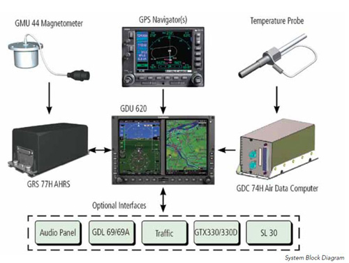
The G500H is optimized for the rotorcraft market and builds upon the best features of the G500 and G600 systems that are for designed for the fixed-wing aircraft market. Specially adapted to the needs of helicopter operators, Garmin’s helicopter synthetic vision technology (HSVT) brings a graphical perspective to the G500H. Available as an option, HSVT can make a difference when visibility is less than ideal. The G500H system is composed of line replaceable units (LRUs) that incorporate a modular design which greatly eases troubleshooting and maintenance tasks when required. A failure or problem can be isolated to a particular LRU that can then be replaced easily and quickly. Each LRU performs a system function or set of functions that contribute to the system’s overall operation. The following LRUs are standard with the G500H system:
• GDU 620 display control unit
• GRS 77H attitude and heading reference system (AHRS)
• GMU 44 magnetometer
• GDC 74H air data computer (ADC)
• GTP 59 temperature probe
The system can interface with the helicopter’s existing autopilot/flight director or SAS, and also works with the following optional Garmin products:
• GNS 430W or 530W series helicopter terrain awareness and warning system (HTAWS) navigator
• GTX 330/330B traffic
• GDL 69A satellite data link receiver
• SL 30 NavCom
• ADF
• GTS 800 series traffic
• Audio panel
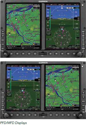
The G500H avionics display system is an avionics suite designed to replace the traditional flight instrument cluster. Dual 6.5-inch LCD screens, mounted side-by-side in a single bezel, put primary flight display (PFD) and multi-function display (MFD) capabilities right in front of the pilot for easy scanning and interpretation. The PFD screen shows attitude, airspeed, altitude, climb rate and course/heading information. The MFD provides detailed moving-map graphics depicting the helicopter’s current position in relation to ground features, chart data, navaids and flight plan routings.
Available in two versions — one with the primary flight display (PFD) on the right, the other version with the PFD on the left — the G500H offers maximum installation versatility. The system is designed so that it can be installed in a single or dual configuration. Installation is typically done by an authorized Garmin Dealer. The installation itself is straightforward and there are no special mechanical or electrical considerations to take into account. Since this is a digital system, all system communications between LRUs is over RS232, RS422, RS485, ARINC 429 and Ethernet buses.
Databases
The G500H avionics display system uses secure digital (SD) cards to load and store various types of data. The cards fit in a slot on the bottom of the GDU 620. The navigation database is updated on a 28-day cycle. It is provided by Garmin and can be downloaded from the specified Garmin Web site. The optional ChartView database is updated on a 14-day cycle and is provided directly by Jeppesen.
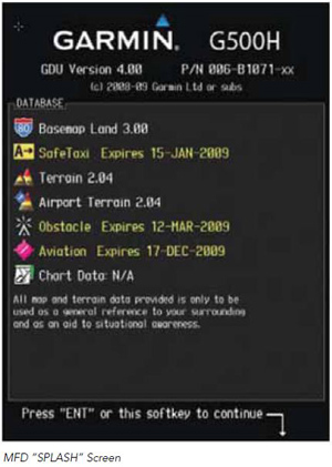
Other databases are Terrain, Airport Terrain, Obstacle, Safe Taxi and FliteCharts. The process of updating the databases is easy to accomplish.
1. Download the data to the data cards from the appropriate Web site.
2. Insert the Navigation Database SD card into an empty card slot on the GDU-620. The SD card with any of the other database data is typically loaded into the lower card slot on the GDU 620.
3. Apply power to the G500H System and view the MFD “Splash” screen. Check that the databases are initialized and displayed on the screen. When updating the Terrain and FliteCharts databases, an “in progress” message may be seen. If this message is present, wait for the system to finish loading before proceeding. Some databases can take up to 15 minutes to load.
4. Follow the instructions in the appropriate Garmin support documentation to finish the data load.
If you have ever loaded software into your PC from a DVD, CD-ROM or other media, then this is pretty much the same thing.
Maintenance
From the maintenance perspective, the G500H avionics display system employs built-in test (BIT) and no special ground support equipment is required. Special attention is given to the cleaning of the display screens. The GDU 620 PFD and MFD displays are coated with a special anti-reflective coating that is very sensitive to skin oils, waxes and abrasive cleaners. CLEANERS CONTAINING AMMONIA WILL HARM THE ANTI-REFLECTIVE COATING. It is very important to clean the screens using a clean, lint-free cloth and an eyeglass lens cleaner that is specified as safe for anti-reflective coatings.
All of the LRUs are replaced on-condition. There is no preset interval at which any LRU has to be tested. Likewise, there are no field adjustments or preventative maintenance tasks that must be performed on the system.
Line maintenance on the G500H system is relatively simple. The status of the system can be checked anytime the system is operating, either on the ground or in the air. The system status page, which can be called up on the MFD, displays statuses, serial numbers and software versions for all detected LRUs. If an LRU is working properly, a green checkmark is shown next to its designation. If the LRU is not working properly, a red X is shown next to its designation. The page also displays installed database information. System annunciations and alerts are displayed on the PFD and MFD.
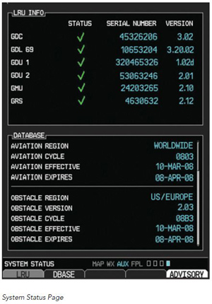
System Status Page
Should an annunciation or alert indicate that an LRU has failed, there are two methods Garmin has in place to correct the problem. If the operator is designated as a “fleet” operator and has applied to Garmin and been accepted as a qualified Part 145 service center, that operator has the ability to troubleshoot the system further using the appropriate maintenance documentation to remove and replace the affected LRU and perform the return to service procedure. If the operator does not meet the criteria called out in the first scenario, then the additional troubleshooting and maintenance tasks should be performed by an authorized Garmin representative that has access to Garmin’s maintenance documentation. Again, the task of removing, replacing and performing the return to service procedure should be performed by an authorized Garmin representative.
Garmin avionics for helicopters…it’s GPS and a whole lot more.