

Shielding Your Engine from Performance Killers
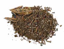
Dirt, dust, salt and sand are the enemies of efficient, reliable and safe turbine engine performance. The effects of their ingestion rob a turboshaft engine of its ability to produce the power required for a helicopter’s mission. They drive increased unscheduled removals, add tens of thousands of dollars to maintenance and overhaul costs, and shorten the economic life of the aircraft. Ultimately, the negative effects of these contaminants could lead to the loss of an engine or lack of power at a critical moment.
FOD
With its vertical takeoff/landing and hover capabilities, the helicopter is more vulnerable to airborne contaminants than a jetliner. Fixed-wing aircraft spend the biggest portion of their flight time in cruise at altitudes measured in thousands of feet, where the air is relatively clean and cool. But helicopters spend substantial amounts of their flight time taking off, hovering and landing.
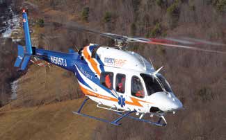
Helicopters perform medical scene landings at unprepared sites, fly marine pilots from freighters into ports, or shuttle oil and gas crews through salt-laden air to offshore platforms. They insert firefighters and drop water through the smoke plumes of forest fires. They carry VIPs or heavy construction loads over all sorts of operating environments from deserts to heavily-polluted metropolitan areas.
Whether helicopters are operating at sea level or in 10,000-foot mountainous terrain, they do most of their work within hundreds of feet of the ground or less where the air is thick with contaminants and hotter than it is at altitude. This fouled, hot operating environment demands that a helicopter’s performance margins be protected from contaminants’ degrading effects.
Dirt/Dusty Environment
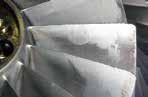
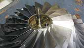
When these contaminants strike rotating compressor components spinning at thousands of rpms, they can erode blades and stators quickly, resulting in increased tolerances. They also can wear down components in the turbine section, where high temperatures can soften the foreign material into a glaze that adheres to its blades and stators. Salt ingestion contributes to internal corrosion and sulfidation of metal components in an engine. This foreign material can block cooling passages and lubricating ports, and cause turbine blade vibration and fatigue problems.
The basic purpose of engine air filtration is to separate contaminants from air entering the compressor and flowing through the combustion section and turbine. Beyond that, engineers seek to optimize a filtration system by maximizing its ability to clean incoming airflow while minimizing:
- The disruption of air flowing into the engine
- The pressure drop across the filter mechanism
- Maintenance requirements of the filtration system and interference with normal operations like pre-flight inspections and continued flight, should the system lose the ability to filter engine airflow adequately.
Filtration Options
Filtration options separate contaminants from air entering an engine in one of two ways: they place a physical barrier with a filter medium in the contaminants’ path, or in a typically less-effective debris capture approach, use physical force in form of vortex tubes to leverage the contaminants’ higher weight (in comparison to air particles), moving them out of the air stream.
Physical Barriers
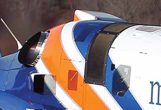
Physical engine protection barriers at the least effective level consist of a mesh screen. However, today’s most effective protection consists of a filter medium (of natural or synthetic material) and seal mounted in an aluminum alloy or composite frame positioned in the engine fairing, over the inlet area. These devices are known as inlet barrier filter systems or IBFs.
An advanced barrier filter may use a specifically-designed screening mechanism and filter medium with aerodynamic fairings and channels to guide clean air into the engine efficiently. The filter medium may be used dry or supplemented with a mineral oil that increases its capture efficiency. The interstices formed by the screen and the dry or wet filter medium are designed to be small enough to block contaminant particles ranging in size from one to 150 microns from entering the engine. The advanced filter also may include a bypass option to ensure airflow to the engine if flow through the medium is inadequate.
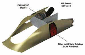
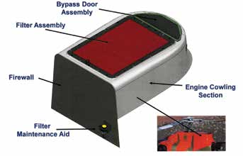
Donaldson’s IBFs utilize a sealed plenum design of sheet metal, machined aluminum and super plastic-formed aluminum parts. The design replaces the OEM’s original engine cowling and less efficient engine air particle separator (EAPS) or foreign object debris (FOD) screen assemblies. In some cases, the IBF housing mounts to the aircraft’s engine door structure. IBF installations for twin-engine helicopters consist of left-hand and right-hand assemblies.
The fairing assemblies maintain the clean, aerodynamic shape of the helicopter. IBF designs typically have a lower aerodynamic drag profile than the helicopter’s existing inlet particle separator (IPS). An adapting structure made of corrosion- and erosion-resistant sheet metal and machined aluminum parts provides mounting provisions for the main filter assemblies.
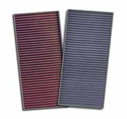
Each Donaldson IBF filter assembly includes multi-layered filter media compressed between two layers of pleated stainless-steel screen and saturated with specially formulated oil. The oil creates a tack barrier that increases the filter assembly’s capture efficiency. The filter assembly allows air flow to the engine over the entire pleated surface area. Air passes through it with a very low drop in pressure, yet the media traps nearly all dirt, dust, salt and sand particles before they reach the engine.
Unlike traditional particle separator or FOD screen designs, each Donaldson IBF unit features a bypass system to ensure proper airflow to the engine in the case of filter restriction. A differential pressure sensor mounted on the adapter structure monitors debris loading in the filter, measuring pressure across the filters. When the differential pressure sensor reaches a defined setting, it activates an easily viewed and pilot-accessed cockpit annunciator/switch. The IBF system includes a filter maintenance aid (FMA) that provides pre- and post-flight indications of filter contamination levels and measures IBF plenum pressure versus ambient air pressure across the filter system to determine maximum pressure drop. It also assists in verification of post-cleaning effectiveness. The FMA provides the ability to perform “on-condition maintenance” of the IBF system between established cleaning intervals.
Physical Force
Dirt, dust, salt, sand and other contaminants weigh more than the air in which they are suspended. This is why they settle over time onto the ground and other surfaces. Engineers leverage this weight difference by designing filtration systems that spin incoming air radially through the use of swirl/vortex tubes or engine bleed air that introduces the spin in a chamber placed ahead of the engine inlet. The spin exerts a centrifugal force that pushes heavier particles like contaminants away from the engine’s longitudinal axis. This enables the separation of that dirtier outer air from the clean inner flow.
This is the basic function of inertial particle separator systems, which includes inlet particle separators (IPS) and engine air particle separators (EAPS). Such systems generally differ only in what they do with the dirty airflow. Some systems direct dirty air through a scavenge duct that removes the contaminants, then re-directs the clean air back into the engine. Others dump the dirty air overboard. Such filtration systems may be available as an integral element of a larger, higher-performance turboshaft engine, or as a module for installation in them, or as a factory or retrofit option.
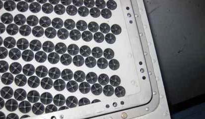
Filtration systems that use swirl/vortex tubes assemble those tubes in panels placed ahead of the engine inlet to clean incoming air. The scavenged air is collected from each tube and dumped overboard.
EAPS use a screened plenum chamber ahead of the inlet to impart centrifugal force to incoming air with a stream of engine bleed air. An EAPS also may use a physical barrier medium to supplement filtration.
Compelling Investment
Helicopter operators are constantly under pressure to control costs better. That drives an intense focus on maintenance, which is a major contributor to operating expenses. With scheduled engine overhauls costing $160,000 to $350,000 an engine, and unscheduled engine repairs costing $70,000 or more, there is a clear need for an effective means of controlling overhaul costs and unscheduled removals by eliminating foreign-contaminant damage to engine components.
When you add to those maintenance costs the price of a helicopter’s lost ability to generate revenue or perform key missions during unscheduled maintenance, the return on investment in an effective engine barrier filter becomes compelling.
An Example
Pacific Valley Aviation (PVA) operates two Bell UH-1H ‘Huey’ helicopters for aerial spraying/application flights in the fertile Sacramento River Valley of northern California. The company equipped its ships with Donaldson IBF systems following substantial engine damage expenses while equipped with IPSs.
Prior to the IBF install, PVA would only get 1,400 flight hours from an engine before needing overhaul due to degradation. This led to reduced flight time and increased maintenance expenses. Now operating with IBFs, the company regularly achieves a 2,400-hour engine overhaul cycle without interruption.
Determining the right filtration system for your helicopter(s) depends on a number of factors. Foremost among these are the aircraft’s operational environments and tempo. Others include filtration system costs, maintenance costs and efficiency. Each filtration option has advantages and disadvantages.
No matter the type of helicopter you operate, having quality engine protection systems in place is a key part of lowering programmatic operating costs. Can you afford to wait to protect your program’s budget via engine damage reduction?
If you would like more information about Donaldson IBFs, visit www.DonaldsonAerospace-Defense.com, or call (952) 887-3131.