

Vertical Gyros Avionics with a Spin to Them
Attitude, heading, altitude and airspeed are four very fundamental and important flight parameters for a pilot. Most of the time pilots don’t even think about where this information is coming from — they just look at the data on their displays and it gives them a picture in their brain of where their aircraft is in the air right now.
Typically this can be separate instruments for each flight parameter or an electronic display that combines all of these parameters on one or two displays in the pilot’s prime viewing area. Altitude and airspeed are air data parameters and we can discuss those in another article at another time. Heading is computed by a directional gyro system and again, we will discuss it in another article at another time.
There are currently three categories of sensors used in helicopters that output attitude data. To clarify this for a moment, by attitude data I am referring to the helicopter’s pitch attitude (nose up or down) with respect to the horizon and its roll attitude (bank angle) with respect to the horizon. Getting back to our three categories of sensors, they are:
• Spinning mass vertical gyros.
• Attitude Heading Reference Systems (AHRS)
• Inertial Reference Systems (IRS) — IRS, sometimes referred to as laser gyros, provide quite a bit more data than just attitude and are not found in too many helicopters due to their high cost. In this article, I will limit our discussion to a conventional spinning mass vertical gyro.
From the maintenance specialists viewpoint, it is important to understand the principles of how the spinning mass vertical gyro operates to better understand what to do and not to do when troubleshooting or removing and installing it. Yes, the Instructions for Continued Airworthiness (ICA) or the Aircraft Maintenance Manual (AMM) will tell you how to troubleshoot and remove and replace it, but not why you do or do not do something.
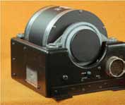
Spinning Mass Vertical Gyro
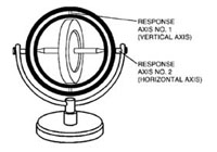
Pictured below is a typical spinning mass vertical gyro. As we stated earlier, its function is to provide an output of actual aircraft pitch and roll attitude with respect to the horizon.
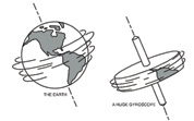
A spinning mass vertical gyro is so named because it has a spinning mass or wheel, universally mounted so that only one point (its center of gravity) is in a fixed position. The wheel is free to turn in any direction around this point. This is similar to the earth spinning on its axis.
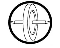
The gyro is supported by a gimbal ring with bearings on which the rotor and its axle can revolve.
Add an outer gimbal ring with bearings at 90 degrees to the rotor bearings, about which the inner gimbal ring with its rotor and axle can turn.
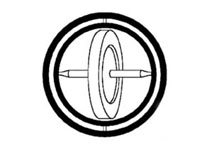
Add a frame that supports the rotor and its gimbal rings on horizontal bearings. Disregarding the spin axis, the gyroscope has two degrees of freedom. The assembly can turn about a vertical axis (response axis No. 1) and also about a horizontal axis (response axis No. 2).
There is nothing unusual about the gyroscope when at rest. It is simply a wheel universally mounted. You can point its axle in any direction without changing the geometrical center of the assembly.
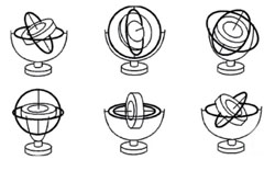
When the rotor spins, the gyroscope exhibits the first of its two characteristics. It acquires a high degree of rigidity and its axle keeps pointing in the same direction, which in this case is the surface of the earth.
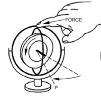
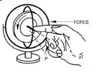
The second characteristic, precession, can be shown by applying a force to the gyro about the horizontal axis. The applied pressure meets with resistance and the gyro, instead of turning around its horizontal axis, turns (or precesses) around its vertical axis in the direction indicated by the arrow P. Similarly, if a force is applied around the vertical axis, the gyro processes around its horizontal axis as shown by the arrow P below. All of the practical applications of the gyroscope are based on these two characteristics. They are based on the laws of inertia and motion defined by Sir Isaac Newton.
With this knowledge, the vertical gyro was born. The rotor system on a helicopter also acts in this fashion. Move the cyclic stick forward and minimum blade pitch angle is either over the left or right side of the rotor system (depending on the direction of main rotor blade rotation), and the blade flaps low over the nose of the aircraft.
As the aircraft pitches up or down, the spinning mass stays in place and a gimbal ring moves with the helicopter around the spinning mass. By connecting an electrical pick-off to the gimbal ring, the vertical gyro outputs an analog representation of pitch attitude. So many millivolts per degree of movement, and this output is used to drive the attitude sphere on the display and for other systems on the aircraft that require an attitude input.
Likewise, as the helicopter banks left and right, the spinning mass again remains fixed in position and the helicopter and other gimbal ring move around the spinning mass. Again through the use of an electrical pick-off to the gimbal ring, the gyro outputs an analog representation of roll attitude. So many millivolts per degree of movement, and this output is used to drive the roll attitude sphere on the display and again for other systems on the aircraft that require a roll attitude input.
This type of gyro is sometimes referred to as a “displacement” gyro. It is so named because the aircraft has to move or displace a certain amount for the gyro to detect the movement. Perhaps a better way to explain this is as follows:
The aircraft is at rest. As it first starts to move nose up, it is accelerating. From this acceleration, we can mathematically determine a rate of travel and from the rate of travel we can again mathematically determine how far the aircraft has moved or displaced over time. The displacement gyro does not have the capability to measure the acceleration or rate of change, so it can only measure and output displacement. This output is generally seen as degrees of pitch and roll displacement from a wings level, nose level attitude.
The handling of this unit is very important to its good operation and long life. I have seen gyros marked “handle like eggs.” Unfortunately, some maintenance personnel think in terms of hard boiled rather than fresh from the chicken. When the gyro is powered up and the spinning mass is rigid in position, the gyro is almost impervious to damage. When the gyro is not in the aircraft and is being moved from one place to another, the spinning mass and gimbal rings are loose and can be banged against their travel stops and over time that will cause damage to the gyro. I suggest that if a gyro has to be removed and replaced and the manufacturer’s shipping container is not immediately available, have some sort of padded container to put the old gyro in so that it is protected from physical abuse.
Another way the vertical gyro can be damaged is through the movement of the aircraft after power has been removed from the gyro. Typical gyro spinning mass speeds exceed 20,000 rpm when under power. When power is removed, the spinning mass starts to slow down. To come to a complete stop can take a few minutes. This is when the gyro is again susceptible to damage. As the gyro spins down, it will nutate or wobble. It is not fully rigid and it is not stopped. If the aircraft is moved at this time, it can cause the gimbal rings to bang very hard against their stops and again over time cause damage. Here is the rule of thumb I offer you to consider: once power has been removed from the aircraft, if the aircraft must be moved, do so completely start to finish in 60 seconds. If you cannot meet this criterion, then wait five minutes after power has been removed before you move the aircraft. This gives the gyro’s spinning mass time to wind down and come to a complete stop.
I hope this helps you better understand how the gyro’s moving parts work and in doing so help you to take better care of your spinning mass gyros and prolong their Mean Time Between Failure (MTBF).