
Avionics Architecture From Then ‘Til Now
R. Fred Polak | Editor
Over the past 30 years, commercial helicopters have been called upon to fly a vast variety of missions. These missions include everything from airborne law enforcement, off-shore oil support, emergency medical support, logging operations, executive transport, etc. This versatility is accomplished by there being many different types and sizes of helicopters. One type and size does not fit all.
Likewise, there are large choices of avionics systems available to enhance accomplishing the mission and improving safety of flight. In many cases, what the avionics systems are designed to do have not changed over time, but their architecture has. Altitude, airspeed, attitude, and heading 30 years ago are still altitude, airspeed, attitude, and heading today. With computers so prevalent in our day to day lives, it is easy to see how they also have become a dominant force in avionics systems. What used to be done with hardware is now being done with software.
With the possibility of having many different helicopters and accompanying avionics systems to support, the helicopter avionics specialist finds it becomes increasingly important to understand the architecture of a particular system to better maintain, troubleshoot and repair that system to the line replaceable unit (LRU) level.
If the system is analog in nature, what test equipment is required? If it is digital, is test equipment needed or does the system have Built-In-Test (BIT)? Does the system require a software load and how long does that take? Having said that, let’s discuss the three main architectures the avionics specialist has to contend with in today’s helicopters - the federated, integrated and distributive type systems.
Analog systems are federated systems. If you are a Star Trek fan, you know about the United Federation of Planets (UFP). The UFP were a large group of planets and colonies that maintained their individuality, but at the same time worked towards a common goal. Federated avionics systems work in a similar fashion in that there are individual LRUs that have a specific task or tasks; together they work as part of a larger whole.
As an example, a helicopter manufacturer may partner with an avionics manufacturer to offer a complete avionics suite of systems on a particular helicopter model. Individually each LRU performs a task or tasks that overall supports a function of the suite. An example of a federated system is shown in Figure 1. Each LRU communicates with other LRUs over discrete wires or in some cases an analog form of bus.
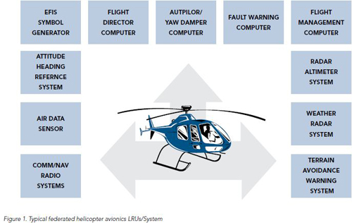
On the plus side, the federated system has many capabilities. On the minus side it has many LRU’s that take up quite a bit of space, requires a large amount of wiring and power, and then there is the weight factor. In helicopters, as in fixed wing aircraft, the Holy Grail for avionics is to do more, with less weight, space and power. Federated systems have been around for a long time. From a maintenance perspective the LRUs generally have their own troubleshooting procedures and specific test equipment. In some instances when a problem is found, the LRU has to be returned to the avionics manufacturer as only they can repair it. This adds to the expense of maintaining the system.
Somewhere between federated and integrated systems, a step was taken from the analog world into the digital world. Some LRUs went from so many millivolts per whatever to a set of one’s and zero’s per whatever. The word “microprocessor” became the word for the day and LRUs became less component intensive and smaller in size.
The next step in the evolution of avionics architecture from then till now was the integrated system. With the advent of microprocessors, specific software, very large scale integration and surface mount technology, it was now possible to take an entire LRU and reduce it in size to a single circuit card assembly (CCA). The function of the LRU did not change as it morphed into a CCA; merely its architecture had changed. Imagine the weight and space savings when LRUs are replaced by circuit cards. Now house multiple CCAs in a single housing and replace four or five LRUs with one LRU! This is an integrated system and a typical example is shown in Figure 2.
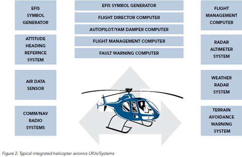
The integrated system is working on the Holy Grail for avionics in reducing weight, space, power consumption, and wiring. Being digital by design, it usually includes its own built-in-test (BIT) and reduces the need for expensive external test equipment. The integrated system has its own unique maintenance considerations, especially if the CCA’s can be individually replaced in the field. The CCA’s must be protected from static electricity and the person removing and replacing the CCA must be grounded to the same point electrically, just to name a few considerations.
In our journey from then till now, we arrive at the current height of avionics architecture, the distributive system. In the federated and integrated systems we saw that those systems were LRU intensive and for the most part the LRU’s were designed for a specific task or function. The distributive architecture on the other hand is very much like a personal computer (PC). The hardware is generic and designed to run many different software programs. The only catch is that the software must be run by the operating system.
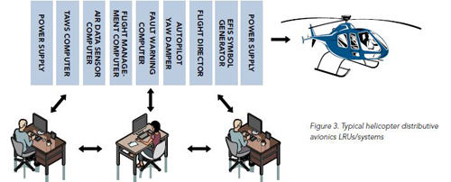
The distributive system reduces LRU weight, space, power consumption and wiring at the next level. LRUs have become modules that fit into a cabinet or rack. Helicopters can have multiple racks and the racks may hold a different number of modules. For the most part the modules are the same from a hardware perspective but run functionally specific software. This scalability gives a distributive system the ability in a cost-effective manner to fit a multitude of aircraft with different avionics requirements. A good analogy would be similar to several desktop computers connected together and sharing processors and memory and the ability to run several software programs at the same time. This is illustrated in Figure 3.
The modules in the distributive system use microprocessors similar to those found in PCs. The use of Commercial Off The Shelf (COTS) hardware helps reduce the cost of engineering specific hardware for each function required. Since the system is now software based, it is also easier for the end user to upgrade changes and improvements to the system. Instead of having to send an LRU back to the manufacturer for an update, it is possible to have the software loadable in the field. The information is displayed on flat panel displays on the flight deck. These could include Primary Flight Displays (PFDs), Multifunction Displays (MFDs) and Engine Instrument and Crew Alerting System (EICAS) displays, just to name a few.
An essential function of a distributive system is information exchange in and between subsystems. Most of the information transfer is accomplished through the use of digital data buses. Some of the data transfer is accomplished in the form of discrete data. Again, this is a tremendous savings on weight and wiring requirements. Another possibility is the use of a local area network (LAN) in the aircraft.
The distributive system also has its own unique requirements when it comes to maintainability. Built-In-Test (BIT) is essential. Test equipment required may include bus readers, dual trace oscilloscopes and signal generators (to checkout bus wiring). Again, in removing and replacing modules it becomes imperative that the procedures called out by the avionics manufacturer and those listed in the Aircraft Maintenance Manual (AMM) be strictly adhered to. Static electricity, grounding, handling and shipping can all be problems and should not be taken lightly.
Data loading is another maintenance function that is taken to a new level. Typically this function can only be accomplished on the ground and is interlocked in some fashion. File integrity is checked by BIT of files within the loadable module. File versions are normally checked by system configuration monitoring software. Inadvertent or incorrect loading results in inoperative units and displayed EICAS messages.
Lastly, due to the complexity and capabilities of distributive systems, many of them have followed the lead of their counterparts flying in commercial airliners; they have an on-board maintenance computer, sometimes referred to as a Central-Maintenance-Computer (CMC). In this case, the CMC is a module that resides in the distributive system cabinet or rack. Without the CMC, we are back to doing maintenance troubleshooting as was done in a federated system.
If there are six LRU’s in the system and one fault indication, that indication may not tell specifically which LRU failed. The process of elimination is time consuming, costly, and may prevent the aircraft from completing its mission. With the CMC, and BIT, a fast diagnosis of the problem with a very high reliability rate of success is achievable. The need for special line/ramp test equipment is eliminated and that lowers the overall cost to maintain the aircraft.
There are several maintenance approaches to distributive systems that are currently in play. Some key maintenance features are:
• A single point access to all subsystems.
• The BIT is simple to operate.
• The BIT can be run from both inside the aircraft and from an external access point.
• Maintenance messages are cross referenced to failures and EICAS messages.
• The BIT is able to determine the root cause of a failure and eliminate cascading faults.
Lastly, with an eye towards returning the system and aircraft to a no fault state, the CMC provides EICAS message to maintenance message correlation, and allows the maintenance professional to determine the source of the problem and the necessary corrective action.
The CMC is not intended as the “final judge” of system health for the purposes of airworthiness, dispatch determination and safety. That role is fulfilled by the EICAS display. The indication that a Return To Service procedure has been completed successfully is the clearing of all associated EICAS messages.
What new system architecture is even now on the drawing boards at some avionics manufacturer? Only time will tell. From then till now is an illusion…as now is always changing.