

A Layman’s Guide to Attitude Heading Reference Systems (AHRS)
R. Fred Polak | Editor
Attitude heading reference systems (commonly referred to as AHRS) have taken many shapes and sizes over the years as technology is continually advancing, especially in the area of micro-miniaturization. AHRS is an inertial sensor installation that outputs aircraft attitude, heading and flight dynamics information to flight deck displays, flight controls, weather radar antenna platform and other aircraft systems. The AHRS differs from conventional vertical and directional gyro systems in that its gyroscopic elements are rate gyros, which are “strapped down” to the principal aircraft axes. By that we mean that in spinning mass gyros, the spinning mass is isolated from the aircraft frame by a gimbal assembly. In the case of the vertical gyro, the spinning mass would erect to the local vertical (earth’s surface) and as the aircraft pitched up or down, the gimbal rings move around the spinning mass which stays vertical. The amount and direction of the gimbal movement represents the aircraft’s movement. In the AHRS, the spinning mass is tied to the aircraft’s axis and moves with it. The output is a rate of change rather than a displacement.
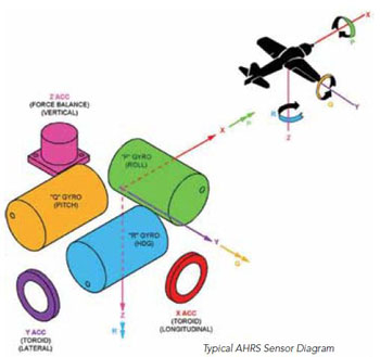
As the name implies, AHRS is a combination of sensors in one package. It replaces the traditional vertical gyro for aircraft pitch and roll attitudes, the directional gyro for aircraft heading, usually used in combination with a flux valve or magnetometer to detect the horizontal component of the earth’s magnetic field, and a rate gyro to detect the aircraft’s yawing motion. The AHRS typically contains three rate gyros to measure angular aircraft motion in the pitch, roll and yaw axis and three accelerometers to measure aircraft linear motion along the longitudinal, lateral and vertical axis of the aircraft. This allows the AHRS to replace six separate line replaceable units (LRUs) with one LRU. This reduces the footprint, weight, wiring and power requirements dramatically.
Another advantage the AHRS offers is improved performance over existing vertical and directional gyros. In a conventional vertical gyro, automatic vertical erection is cut off when the roll angle, or in some cases the pitch angle as well, exceeds a certain value, typically five to 10 degrees. This causes the conventional gyro to produce a vertical error proportional to its free drift during extended large bank angle maneuvers. A related problem concerns shallow bank angles just below the cutoff. In this case, the automatic erection loop causes the gyro to erect to the false vertical induced by the turning acceleration.
The AHRS uses a velocity damped Schuler-tuned vertical erection loop used in advanced military and commercial strapdown systems. This type of loop eliminates the need for small erection cutoff angles and maintains continuous erection to the true local vertical under all normal flight maneuvers.
Conventional gyros are also susceptible to gimbal lock under certain conditions. The AHRS is an all-attitude system and is free from such problems. Modern flight control systems can make effective use of rate and acceleration feedback terms. These terms, which are not directly available from simple vertical or directional gyros, were derived from position data or from extra rate gyros and accelerometers. The AHRS directly measures these quantities and supplies all required data for the digital automatic flight control system (DAFCS) in both earth-based and aircraft body axis coordinate reference frames.
On the plus side, an AHRS requires less power, less wiring, weighs less and has a smaller footprint than installing the three gyros mentioned above. On the negative side, it probably costs more. Aircraft OEMs are constantly looking at the trade-off between cost, weight and reliability in determining what avionics they want to put in their aircraft.
A Typical System
An AHRS is usually made up of the following LRUs.
• An attitude heading reference unit (AHRU)
• A flux valve or magnetometer
• A controller or panel-mounted switches
• A configuration module
What’s in the box?
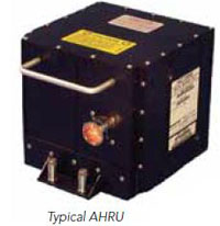 The AHRU is the major component of the system. It contains the necessary power supplies, rate gyros, accelerometers and electronics to compute aircraft attitude, magnetic heading and rate of change and acceleration forces. Depending on who manufactures the AHRU, it can output analog/digital data for aircraft systems as required.
The sensors can be of many different types, depending on when the AHRU was made and what technology the avionics OEM was employing at the time. In the early days, the gyros were spinning mass rate gyros. There would be one each for the pitch, roll and yaw axis. The next generation was fiber optic rate gyros. They were an improvement over the spinning mass rate gyros as there was a significant reduction in moving parts. No gimbal assemblies or spinning masses, just photons traveling through a cable assembly. The next generation was a laser gyro unit. If you are familiar with some business jet inertial reference systems (IRS), this is just like them, but the navigational capability is not there. Again, there are less moving parts and photons traveling through a cable assembly. The downside is cost, as the laser gyros are expensive. The latest and greatest sensors are solid state, employing micro electro-mechanical system (MEMS) technology. Imagine a rate gyro the size of your thumbnail!
The Cobham ADAHRS shown is a combination of digital air data and solid-state AHRS all in one small package utilizing MEMS technology. It consists of the ADAHRS unit, a magnetometer and an outside air temperature (OAT) probe. The three- component suite weighs in at less than 1.5 pounds and has an MTBF of 13,000 hours.
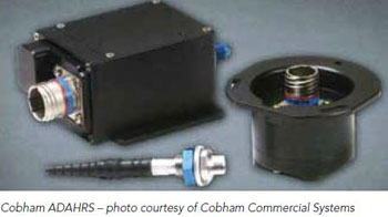
As you can see, the AHRS is getting smaller, lighter and more reliable as time moves on, and in some instances, is being combined with air data sensors to really improve on weight, space and wiring requirements.
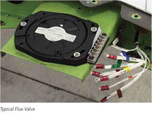
The flux valve/magnetometer is used to detect the horizontal component of the earth’s magnetic field and provides the long-term reference for heading data. Its function is the same as it has been for fixed- and rotary-wing aircraft using spinning mass directional gyro systems. Typical commercial AHRS do not provide an output of true heading. True heading is typically associated with commercial and military inertial reference systems and flight management systems.
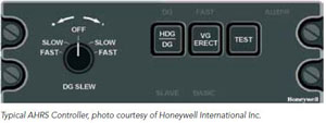
The AHRS controller, as its name implies, hosts the switches that tell the AHRS what mode to operate in, as well as some important annunciators. Some installations do not use a controller per se, but rather have individual switches and knobs installed in the instrument panel and/or pedestal. A typical AHRS controller is shown. For specific switch functions in your installation, always refer to the manufacturer’s operating manual.
The configuration module, like the controller, may not be a part of all AHRS installations. If it is present, it is used to provide the system with information such as AHRU configuration discretes (in which direction in the aircraft is the unit facing), mounting misalignment coefficients and flux valve mounting coefficients. Programming of the module is typically performed with a laptop computer. Memory module configuration data is usually programmed during aircraft installation of the AHRS. Subsequent replacement of either the configuration module or the flux valve requires the configuration data to be reprogrammed, and the flux valve to be recalibrated in accordance with the procedures in the aircraft maintenance manual (AMM).
Troubleshooting Information and Considerations
Typically the AHRU that is not employing MEMS technology is installed on a tray that has been aligned to the aircraft axes using special tools. The tray provides positive indexing of the AHRU to the aircraft, thus eliminating any requirement for re-leveling when maintenance or replacement of the AHRU is required.
Longitudinal alignment of the tray to the aircraft may be at any 90-degree increment, permitting installation in an increased number of previously unacceptable locations. Many AHRS have different modes of operations and to familiarize yourself on what each mode will and will not do, refer to your AHRS manufacturers operating manual.
Troubleshooting any system is an art form. To overlook the obvious can lead to hours of unnecessary work and expense. If we are in North America and are looking for a four-legged animal, it makes sense to look for dogs, cats and horses before we look for giraffes, zebras and hippos. In troubleshooting the AHRS, we need to apply the same logic. Is the discrepancy valid for the switch/knob positions? Is the discrepancy valid for the operating mode selected at that time? Lastly, was a maintenance action performed on or around the AHRU, and did the discrepancy occur after the maintenance action was completed?
One of the most frequent problems with the AHRS that I have seen over time is the troubleshooting of “heading splits/flags” in a dual AHRS installation. Some concerns that can cause this condition are:
• Area magnetic interference – The earth’s magnetic field can be disturbed enough to cause this by positioning the aircraft in close proximity to any large piece of metal that would influence the flux valve/magnetometer. If possible, avoid positioning the aircraft close to jetways, power carts, tow tractors, power carts, hangar and steel-reinforced ramps. When troubleshooting a heading split/flag discrepancy, avoid these conditions.
• Aircraft magnetic interference – Any ferrous metals located within one meter of a flux valve/magnetometer are generally referred to as a hard iron error. An easy way to detect magnetic screws or materials is to hold a hand-held compass above the flux valve/magnetometer,slowly move it from the front to the rear of the flux valve, and look for any heading changes on the compass as you do so.
• Flux valve/magnetometer calibration – Errors in flux valve/magnetometer calibration can cause heading splits. Check that an accurate heading reference is used when performing a compass swing and perform the compass swing on both AHRS at the same time.
• Flux valve/magnetometer or wiring – Although this may be the very last item you check, it is not inconceivable that the flux valve magnetometer itself has failed. To check on the integrity of the unit, make sure all screw connections are tight, no dampening fluid is leaking from the unit, the connectors are corrosion free and all shielding is as required.
• Attitude heading reference unit – Yes, the AHRU itself can be the problem. To see if the AHRU is the problem, first determine what mode of operation the AHRU was in. If the AHRU was slaved to the flux valve/magnetometer reference, perform the following procedures:
- Using the heading of the standby compass as a reference, compare the pilot’s and copilot’s AHRS headings and write them down.
- Swap the pilot’s and copilot’s AHRUs.
- Again, using the stand-by compass as a reference, compare the pilot’s and copilot’s headings and write them down.
If the AHRU is operating properly, the amount of the heading split on a specific side should remain the same. If the heading split does not remain the same on a specific side, that is the faulty AHRU.
If the AHRU was not slaved to the flux valve/magnetometer reference, perform the following procedures:
- Select both AHRS to DG mode (or whatever the mode is labeled) when the AHRS is not slaved to the flux valve/magnetometer reference.
- Using a standby compass as a reference, slew each AHRS heading to the standby compass heading.
- Slowly have the aircraft taxi to different headings; stop and compare the AHRS heading readings to the standby compass heading reading.
If the AHRUs are operating correctly, each AHRS heading should agree with the standby compass heading. If one side does not agree with the standby compass heading, that side AHRU is at fault.
This was just an overview of the more common AHRS found in our industry today. Of course, as with all systems, there will always be problems that are not this easy to troubleshoot. These are just some of the more common discrepancies we have encountered over time. Always refer to the AHRS manufacturer’s AMM for diagnostic information that is relevant to your particular installation.