

A Mechanics Guide to Flight Management Systems
R. Fred Polak | Editor
A flight management system (FMS) is often mistakenly called a long-range navigation system. I say mistakenly because the FMS does more than just long-range navigation. The FMS acts as a navigation manager, and in doing so, reduces the number of system controllers on the flight deck and helps reduce the pilot’s workload. By workload I am talking about the amount of data presented to the pilot on several different displays, and how the pilot analyzes that data and determines what is the best data to use to get from point A to point B. As the navigation manager, the FMS is smarter and faster than the pilot, and can perform intricate calculations quickly on large amounts of data to give the pilot the best way to get from point A to point B.
Wait a minute, you say! Why would we find an FMS in a helicopter? There are several reasons. What is the helicopter’s mission and where is it operating? If we were based out of Phoenix and did 99 percent of our flying within 200 NM of our base, then we would probably not need the benefits of an FMS. On the other hand, if we were operating in the northern wilds of Canada or in a remote part of the world that did not have an abundance of navigation aids, we would want as much navigation assistance as we could get. Most FMS have a navigation data base that has all kinds of information that is useful to the pilot, especially if they are operating in an area that is relatively new to them.
What about using GPS, you ask? Good question, but GPS is a sensor and if it’s not working for some reason, where is your navigation backup? The FMS is connected to several navigation sensors and monitors them all the time. The sensors are not part of the FMS, but are connected to it for the navigation management function. When the GPS fails, it recognizes the failure immediately and ignores the GPS position data and uses whatever else it has to compute the aircraft’s present position. The FMS knows which sensors are the most accurate and looks to see what is available to it. Typical FMS sensor hierarchy would be as listed, assuming all the listed sensors were on the aircraft and functioning.
• GPS - first
• DME - second
• IRS - third
• VOR - fourth
• AHRS (heading only)
FMS Functions
The primary function of an FMS is accurate short-range and long-range lateral and vertical navigation. This is sometimes referred to as LNAV for lateral navigation and VNAV for vertical navigation. Remote flight plan building and storage, creating and storing waypoints, a database containing information on navigation aids (NAVAIDS) and earth reference points such as airports, intersections, runways, routes and radio tuning are also FMS functions.
The FMS gives lateral and vertical navigation guidance for display and can be coupled to the aircraft’s automatic flight control system (AFCS) if one is installed in the aircraft.
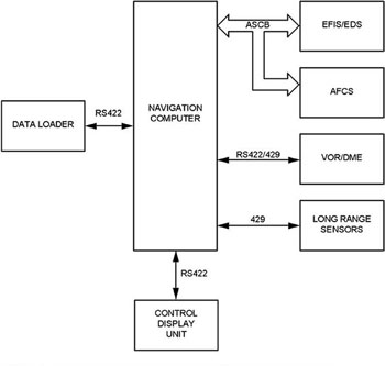
Now that we have discussed what an FMS is, let’s talk in general terms about the line replaceable units (LRUs) that typically are found in an FMS. The typical FMS consists of the following LRUs: a navigation computer, a control display unit and a data loader.
In some instances, the FMS may also have a performance management computer. A typical FMS system block diagram without a performance management computer is shown in Figure 1.
Navigation Computer
The navigation computer is the brain for the FMS. It has two primary functions and multiple secondary functions. The primary functions are position computation and flight planning. These functions work to provide computed guidance in both the lateral and vertical axes of flight. The navigation database (NDB) contained in the navigation computer is essential to these functions. The database is used to store waypoints, navaids, airways, procedures, airports and other navigation data. The NDB is usually updated every 28 days.
The navigation computer connects to a variety of short-range and long-range navigation sensors (see Figure 1). The primary short-range sensors are DME/DME and VOR/DME. Long-range sensors include the global positioning system (GPS) and inertial reference system (IRS). Using the available sensors, the navigation computer develops an FMS position based on a blend or mix of sensor inputs. Based on the position and the flight plan, the FMS generates information for display on the control display unit (CDU) and flight deck displays.
The lateral navigation function of the FMS calculates navigation information relative to selected geographical points. The pilot can define flight plan routes worldwide. The system outputs advisory information and steering signals that show the pilot or AFCS how to guide the aircraft along the desired route. Routes are defined from the aircraft’s present position to a destination waypoint along a great circle route, or through a series of great circle legs defined by intermediate waypoints. OK everyone, stay with me here. We talk about great circle legs and routes because the earth is a sphere and to get from point A to point B on a sphere, you are moving in a circular fashion. So much for navigation 101.
DataBase
The database is generally made up of two separate parts, a navigation data base and a custom database. An FMS world-wide navigation database (the one that is updated every 28 days) would typically include the following data:
• All VOR/DME navaids – their geographic position, radio frequency, altitude above sea level, class of navaid, etc.
• All high-altitude and low-altitude routes.
• All named route intersections.
• All airports that have an International Civil Aviation Organization (ICAO) identifier. (For example, KORD for Chicago’s O’Hare Airport.) All airports in the United States that have an ICAO identifier are prefixed with the letter K. (Good, now you have had navigation 201).
• All the runways, published departures and arrivals for those airports.
The custom database is not updated on any specific time frame. It contains the flight plans and waypoints that have been created by the pilot and stored by a specific name. This gives the pilot the ability to call up and use a flight plan or waypoint that is flown on a regular basis without the need to build it each time it is flown.
Control Display Unit (CDU)
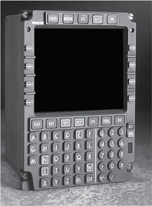
The CDU is the pilot interface to the navigation computer. CDU operation is designed to be simple and to minimize crew work load in all phases of flight. Pilots enter data through the use of an alphanumeric keyboard and line select keys. A typical CDU is shown in Figure 2.
The CDU is the primary pilot interface with the system. Flight plans are transferred between navigation computers over an ARINC 429 bus, and the link to the CDU is over an RS-422 private-line interface. With links to the on-board navigation sensors, the navigation computer develops an FMS position based on a blend or mix of the sensors.
The FMS does not display navigation maps on the CDU directly. However, the FMS is the source of map data for the flight deck displays. The navigation part of the FMS is an area navigation system or RNAV. Its fundamental purpose is to provide navigation information relative to a selected geographic point.
Data Loader
Last but not least in our system is the data loader. This is the LRU that allows the navigation database to be updated with current information every 28 days. In some aircraft it is permanently mounted, while in others it is not and is hand portable to the aircraft. The data loader typically is a unit similar to what you have in your PC that allows you to download and upload information via a CD/DVD or USB interface.
Hopefully this will enlighten you as to the purpose of FMS in general and a bit on how and why they do their thing. If you have any questions and think I can help you with the answer, let me know and I will do my best to help. Who knows? You might be ready to move on to Navigation 301.