

RADALT THE OTHER ALTITUDE
The business of aviation has a language all its own. From flight crew to maintenance specialists, we hear terms such as barometric altitude, pressure altitude, density altitude and something I will refer to now as the “other altitude.” Just how many different altitudes are there?
Barometric pressure is just a measure of air pressure using sea level as the base reference. At any given time within our atmosphere, any place on Earth is subject to the pressure of the air above it. The term “atmospheric pressure” is often used to describe the same thing as “barometric pressure.” These terms describe the pressure of all the air above a given point. Because both gravity and heat energy decrease at higher altitudes, the air pressure also decreases as we rise above sea level.
Standard/Barometric Altitude
Standard barometric pressure at sea level is established as 29.92 in/Hg (Mercury) in the United States, and 1,013 hPa (HectoPascals) in all countries using the metric system. This setting is equivalent to the air pressure at mean sea level (MSL) in the International Standard Atmosphere (ISA). As an example, if our aircraft was sitting on runway 08R at Phoenix Skyharbor Airport, on a standard day our barometric or “baro” altitude would be 1,110 feet. That is our height above sea level. This is the scientifically-accepted baseline for measuring barometric pressure. As you move to higher altitudes, the average baseline pressure will drop. These are, of course, only baseline pressures. The actual pressure will vary depending on factors like location, temperature and current weather fronts. Figures are calculated for the drop in pressure that occurs every 1,000 feet.
Density Altitude
Density altitude is the altitude in the ISA at which the air density would be equal to the actual air density at the place of observation, or in other words, the height when measured in terms of the density of the air rather than the distance from the ground. Density altitude is pressure altitude adjusted for non-standard temperature. Both an increase in temperature, and to a much lesser degree humidity, will cause an increase in density altitude. Thus, in hot and humid conditions, the density altitude at a particular location may be significantly higher than the true altitude. Barometric/pressure altitude and density altitude are commonly referred to as “air data” parameters.
Now, let’s talk about that other altitude, the one that isn’t an “air data” parameter. There are avionics specialists that refer to this other altitude as radio altitude, and others that call it radar altitude. They are, in fact, one and the same and that is why I refer to it as radalt. In this way I am not right or wrong, and everyone can call it what they want. But just exactly what is radalt?
RADALT
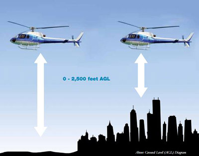
Radalt indicates absolute altitude of the aircraft’s height above ground level (AGL), or whatever might be directly below the aircraft. The system achieves this by transmitting radio waves downwards from the bottom of the aircraft and reading the received reflected signals. The time lapse between transmitted and received signals is then used to calculate the height above what is directly beneath the aircraft, be it the runway, a building, etc.
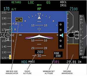
If we take the previous example of our aircraft sitting on runway 08R at Phoenix Skyharbor Airport, we said its barometric altitude was 1,110 feet. For those same conditions, its radio altitude would be zero feet. Therein lies the difference. Radalt is telling the pilot the height from the landing gear or skids to whatever is immediately below the aircraft. This is extremely valuable information on takeoff and landing. Whereas barometric altitude for civilian aircraft may have a limit of 60,000 feet, a radalt typically has a limit of 2,500 feet. Again, since radalt is primarily used in takeoff and landing, there is no need for a greater limit. The radalt information is usually displayed on its own indicator or integrated into a primary flight display (PFD).
Just as barometric altitude data is used by different systems on the aircraft, so is radalt data. Some that come to mind are absolute height above the terrain, decision height (DH) comparison alerting, ground awareness display, flight director gain programming for localizer and glideslope approaches, as well as an input to TAWS and TCAS, to name a few.
Radalt antennas have a fairly large main lobe of about 80 degrees so that up to bank angles of about 40 degrees, the radio altimeter detects the range from the aircraft down to the ground, specifically to the nearest large reflecting object. This is because range is calculated based on the first signal return from each sampling period. It does not detect slant range until beyond about 40 degrees of bank or pitch. This is not an issue for landing, as pitch and roll do not normally exceed 20 degrees or so during approach and landing.
Radalts are usually designed as short-range FM radars operating in the 4.2-4.4GHz frequency band. Their main applications are instrumented approaches and landings of commercial aircraft. The accuracy and resolution of these altimeters is usually limited to a few feet due to the different landing configurations of various aircraft. Most radalts have separate transmit and receive antennas.
As the name implies, radar (radio detection and ranging) is the main principle of the system. Radio waves are transmitted towards the ground, and the time it takes them to be reflected back and return to the aircraft is timed. Because speed, distance and time are all related to each other, the distance from the surface providing the reflection can be calculated as the speed of the radio wave, and therefore the time it takes to travel a distance is a known quantity.
Continuous Wave (CW) Radar
One way to measure the distance to an object is to transmit a short pulse radio signal (electromagnetic radiation) and measure the time it takes for the reflection to return. The distance is one half the product of the round-trip time (because the signal has to travel to the target and then back to the receiver), and the speed of the signal. Since radio waves travel at the speed of light, accurate distance measurement requires high-performance electronics. The receiver often does not detect the return while the signal is being transmitted. Through the use of a duplexer, the radar switches between transmitting and receiving at a predetermined rate.
In aviation, the radar mile is the amount of time it takes for a radar pulse to travel one nautical mile, reflect off a target and return to the radar antenna. Since a nautical mile is defined as 6,080 feet, then dividing this distance by the speed of light (161,875 nautical miles per second), and then multiplying the result by 2 gives a result of 12.36 microseconds in duration.
Frequency Modulation
Alternatively, frequency-modulated CW radar can be used. The greater the frequency shift, the further the distance travelled. This method can achieve much better accuracy for the same outlay, and radalts that use frequency modulation have become the industry standard.
In these systems a “carrier” radar signal is frequency modulated in a predictable way, typically varying up and down with a sine wave or sawtooth pattern at audio frequencies. The signal is then sent out from one antenna and received on another, typically located on the bottom of the aircraft, and the signal can be continuously compared using a simple beat frequency modulator that produces an audio frequency tone from the returned signal and a portion of the transmitted signal. Since the signal frequency is changing, by the time the signal returns to the aircraft the transmit frequency has changed. The amount of frequency shift is used to measure distance, since it is proportional to the time delay between the transmitted and received signals.
Maintenance Tips
Observe the following precautions when performing maintenance on a radalt system.
1. Anytime the antenna(s) are removed for cleaning, they need to be put back in the same orientation. There may be a mark or arrow on the antenna and it should be replaced in the same alignment as it was removed.
2. Anytime the transmit antenna is removed, the radalt circuit breaker should be pulled and tagged to not be reset until cleared to do so by maintenance. With the transmit antenna removed, if power is applied to the radalt transmitter, it is trying to send a pulse into an infinite load. The signal will be reflected back into the unit and burn up the transmitter.
3. Since most radalt systems are generic and can be installed on everything from a Eurocopter AS-350 to a Boeing 747, there is usually a zero adjustment that is to be performed when the unit is installed in the aircraft. Make sure that the manufacturer’s instructions in the AMM or ICA are followed.
I hope this has given you a better understanding of the “other altitude” we work with in aviation. If you want some more information or have some questions, just let me know.