Troubleshooting - PHILOSOPHY 101
Helicopter avionics systems come in all shapes and sizes depending on the aircraft and the mission. There are analog systems, digital systems, federated, integrated and distributive systems. Acronyms abound: TCAS, RADALT, TAWS, AFCS, GPS, WX RDR and EFIS. With the possibility of having to maintain different helicopters with different avionics suites, the following philosophy is intended to act as a guide in verifying and resolving a system malfunction down to the Line Replaceable Unit (LRU) level. Getting it right the first time is what this is all about, reducing maintenance work hours and costs. In this example, the malfunction is in the flight director system, but the philosophy can be applied across a broad spectrum of systems. This philosophy is accomplished by a series of statements and questions asked by the maintenance specialist. Based on the answers received, a path is followed that leads to finding the LRU at fault in a logical and precise manner.
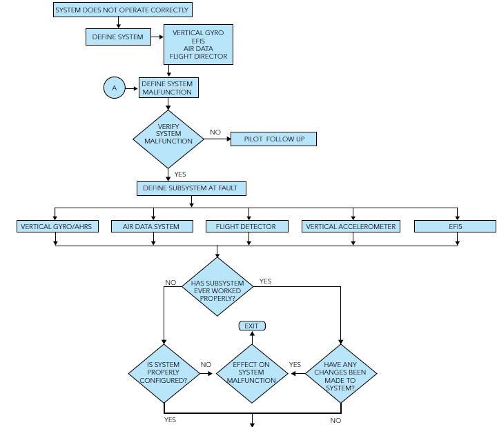
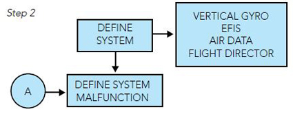
Step 1: When the helicopter returns from a flight and a malfunction is reported, the first step in this philosophy is to define the system at fault. This may sound silly, but the failure of one LRU may cause the failure of another LRU. This is called malfunction “cascading.”

Step 2: With the system defined, the malfunction should be defined with as much information as practicable. Example: Altitude Hold mode does not work properly. There is a problem stated, but a better statement would be: with the autopilot not engaged at a cruise altitude of 6,000 feet and the helicopter in straight and level flight at an airspeed of 120 kts indicated and the Altitude Hold flight director mode selected on, the helicopter porpoises and deviates +200 feet from the selected altitude. This tells the maintenance specialist more specific information. Usually maintenance and flight operations need to get together and work out how best to communicate in-flight problems.
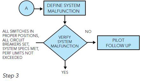
Step 3: After defining the system malfunction, the described fault should be verified as being valid or not valid. Questions to ask are:
• Were all applicable switches in their proper positions?
• Were all circuit breakers set?
•Were system specifications or performance limits exceeded?
A good way to look at this is as such: if we are looking for four-legged animals in North America, we should start with dogs and cats and horses before looking for giraffes, zebras and elephants. In other words, do not overlook the obvious. If we do, it takes longer to find the problem.
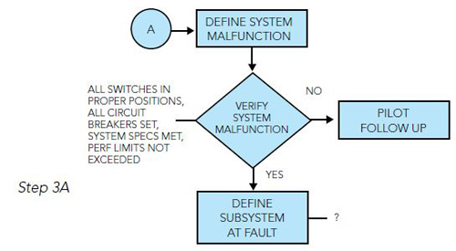
If the fault is not valid, it calls for a detailed write-up explaining why the system is working as it should. If the fault is valid, the next step is to determine if there is a subsystem at fault. A helpful tool here is the Aircraft Maintenance Manual (AMM) or in this instance, the Flight Director System Maintenance Manual, to see if there is a diagram showing what LRUs are used in the Altitude Hold Mode of operation.
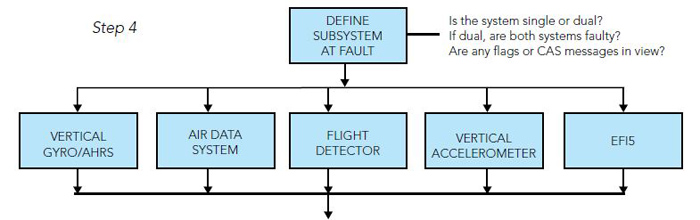
Step 4: All flight director systems can be divided into four parts: sensors, computer, controller and loads. In this scenario, these four parts work to provide the pilot with a computerized vertical steering command to maintain a selected barometric altitude reference. In most instances, a failure in one of the subsystems will cause a partial or full failure of the flight director. Questions to ask are:
• Is the flight director system single or dual?
• If dual, was the malfunction seen on both sides?
•Were any instrument flags or Crew Alerting System (CAS) messages in view?
Looking at the Altitude Hold mode diagram in the flight director system maintenance manual, the subsystems used are:
• Attitude Source
• Air Data System
• Vertical Accelerometer
• Electronic Flight Instrument System (EFIS)
• Flight Director Computer
• Flight Director Mode Selector
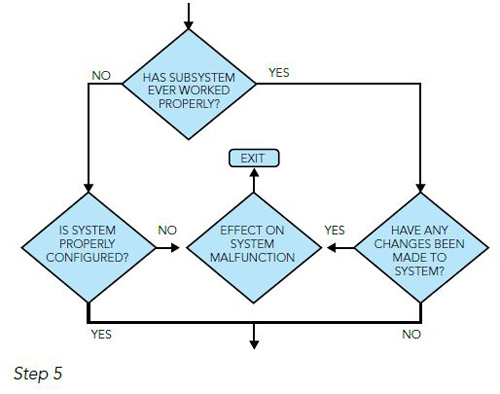
With the subsystem defined, it should be determined if the subsystem has ever worked properly. Far too often, a customer finds that they accepted an aircraft new from the manufacturer, or a previously-owned helicopter from another operator, with a system fault. In other words, the system did not work correctly from day one.
Step 5: If the system has never worked properly, ask the following questions:
• Do all of the LRUs have the correct part number and dash number?
• Are all of the LRUs up to the latest modification level?
• If the system has worked properly before now, ask the following questions:
• Have any system LRUs been removed and replaced recently?
• Has any system wiring been worked on?
• Have any system modifications been done?
• Has any work been done on the helicopter that required any of the affected system LRUs to be removed and reinstalled?
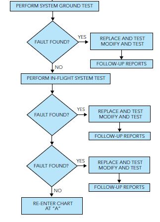
If the determination is such that the system is configured properly and no changes have taken place or affected the system, then a ground test of the system should be performed.
Step 6: A system ground test aids in the fault isolation process by determining if any part of the system is not operating within published specifications. Before initiating the system test, it is recommended that the following things be checked:
• All LRUs are properly seated in their mounting racks.
• There are no bent, loose or broken pins on the LRU and rack connectors.
• There are no broken wires or shields.
• There is no observable corrosion.
After the system is turned on, check for the following:
• The unit is, in fact, receiving power.
• All input signals are present and of the correct gradient.
• All signal outputs are present and of the correct gradient.
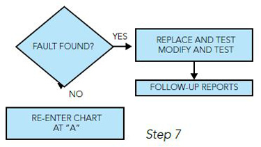
If the fault is found, then the appropriate corrective action can be accomplished.
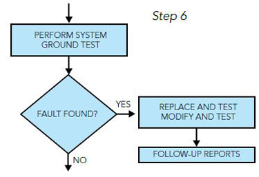
If the fault cannot be isolated with the ground test, then a test flight may be necessary to further recreate the malfunction.
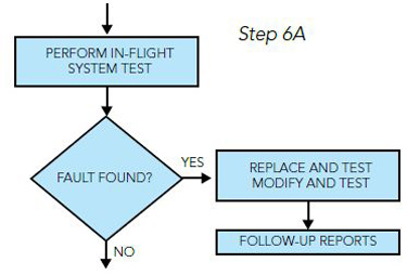
If a test flight is not possible, then it is necessary to redefine the malfunction or the subsystem at fault. Then this troubleshooting philosophy is repeated. Again, please keep in mind that this guide is just that — a tool that can be used to more quickly find and repair a system malfunction to the LRU level.